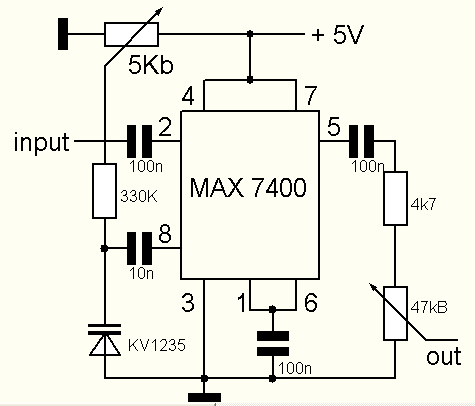
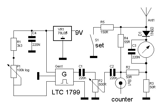
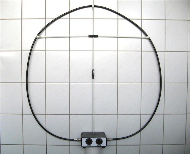
This is a verry simple but good working swr analyzer based on the LTC 1799 smd generator . Tuning is easy: Connect your antenna to the analyser with the meter at full scale and look with the 100K potentiometer for a dip on the meter.
Disconnect the antenna and push the set switch. Now adjust the power for a 1:3 reading on the VSWR meter.Releasing the switch will make the meter jump in to the right corner, but that's normal due to the simple bridgeform . Connect the antenna and read the axact VSWR. The first model had a 6.5 V power suply but this caused the LTC 1799 to warm up and drift. At 5V the current is low and the IC is stable.
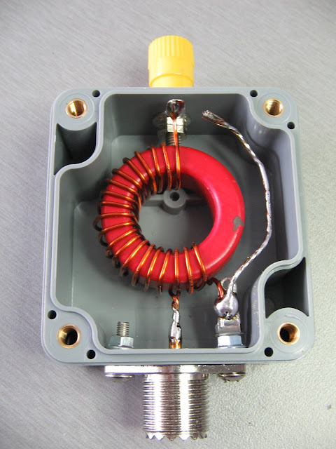
Most components are mounted on the back of a little pcb , the rest is soldered directly on to the meter and " point to point ". To expand the range downwards to about 0.1 MHz , just put a switch between pin 4 of the generator and the ground. If you want to use a counter , put a 1K resistor in series with the connector. Those who want to build in a counter can replace the 100 K potmeter by a 10 turns type and omit the presets.A verry small counter is available by
Hendricks QRP Kits If you are not using a counter , a tuning scale can be made with the help of digital receiver. By lowering the value of C1 the amplitude can be reduced so a more equal power setting can be obtained over all the bands. The meter should have a 100-200 uA reading. PE1IWT did an interesting mod on this analyzer project , you can find it
here .It's in Dutch but the pictures explain it all. This versatile instument offers the novice radio amateur a lot of help with his antenna and balun projects .
![]() |
| VFO TUNING OR PRESETS POSSIBLE |
![]() |
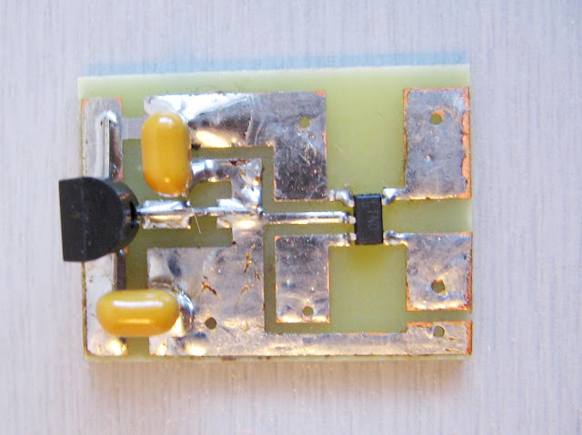
| MINIMAL COMPONENTS |
![]() |
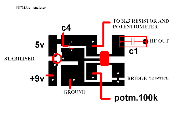
| 1:1 PCB |
![]() |
COMPONENTS ARE MOUNTED ON THE COPPER SIDE
![]() | | NOTE THE GROUNDING OF THE REGULATOR BY A JUMPER |
|
![]() |
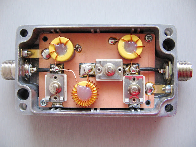
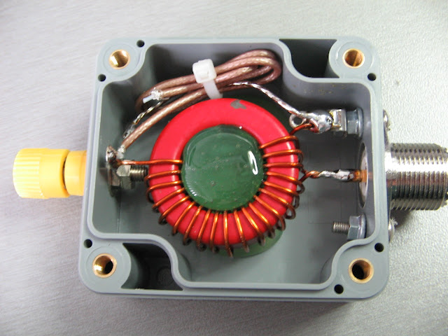
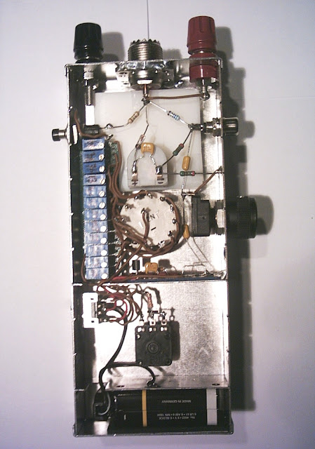
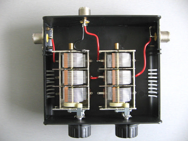
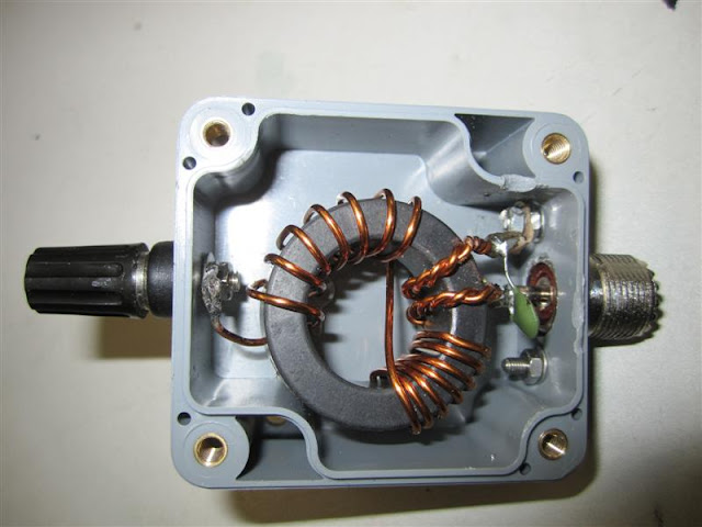
INSIDE VIEUW OF a SECOND MODEL ,MADE FOR AN OTHER HAM
THE PRESET POTENTIOMETERS ARE 10 TURNS TYPES
|
Not to scale alternative pcb suggesture made by carving with a steel scribe
Wil need 2 jumpers to complete


.jpg)
.JPG)